Slicer Software vs. Tracer Software
This “Tracer” software 3D printing method is for extrusion based printing.
This patent-pending method creates self supporting loops by maintaining the same increment along each surface. Each successive loop is equidistant from the previous.
Slicer
Software
Tracer
Software
Comparison between traditional Slicer and this Tracer Software
3D Model
3D Model


This is a simplified 2D view for a 3D model of a vase. In both methods we start with a 3D model
Increment Slices
Increment Traces


Slices are equal increment sections in the z-axis
along z-axis
along surface


Traces are equal increment sections along surfaces
3D view
3D view


Each resulting trace loop is equidistant from the previous loop. Thus, each loop is traced from the previous loop.
For simplicity, the above example was for a rotationally symmetric vase. The resulting tracer print paths happened to be flat. However, this is not often the case. Typically resulting paths are non-planar
The following example of a snub cube results in non-planar tracer print paths.
Slicer
Software
Tracer
Software
3D Model
3D Model


Upload a 3D model STL (.stl file)
First Slice
Seed Loop
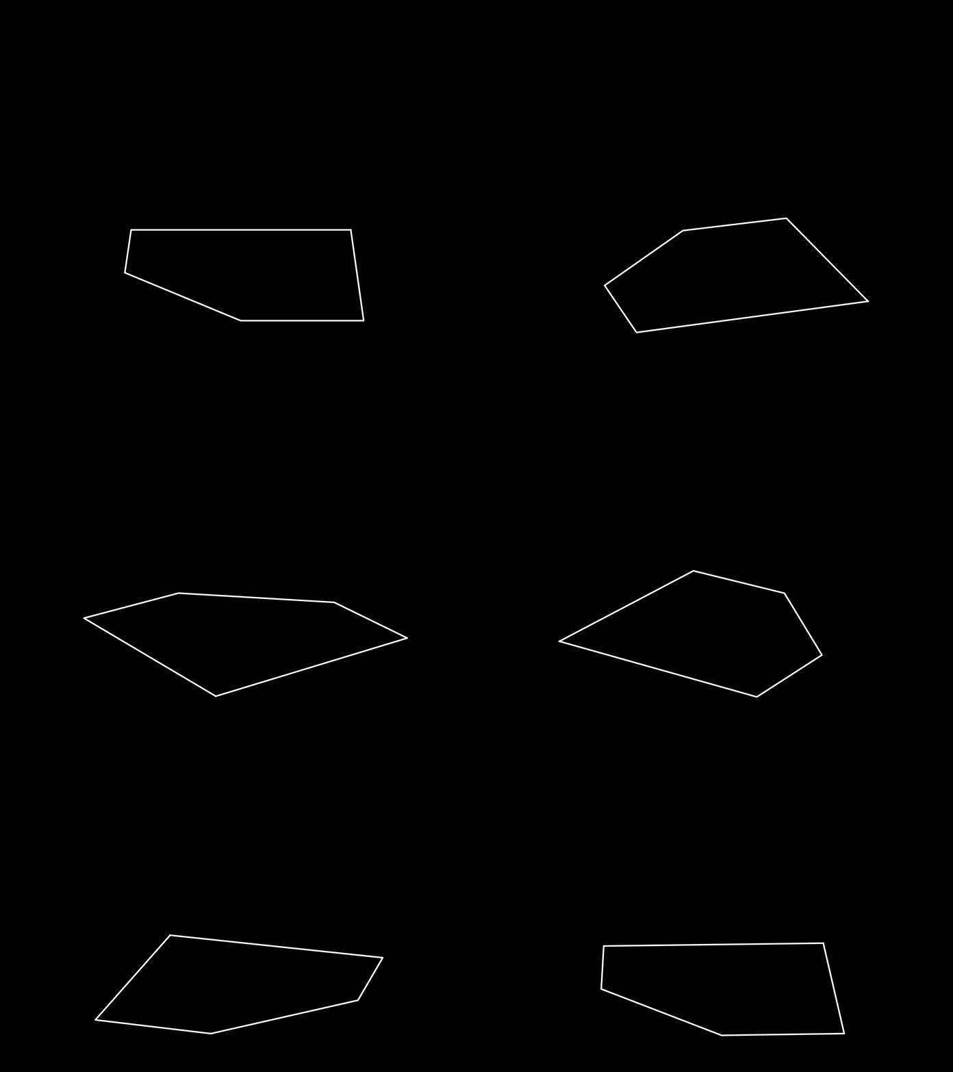

In this tracer case the first (seed) loop is a flat pentagon on the build plate just like the first slice
Z-axis Increments
Surface
Increments
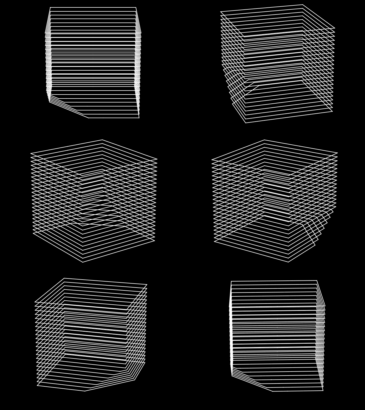
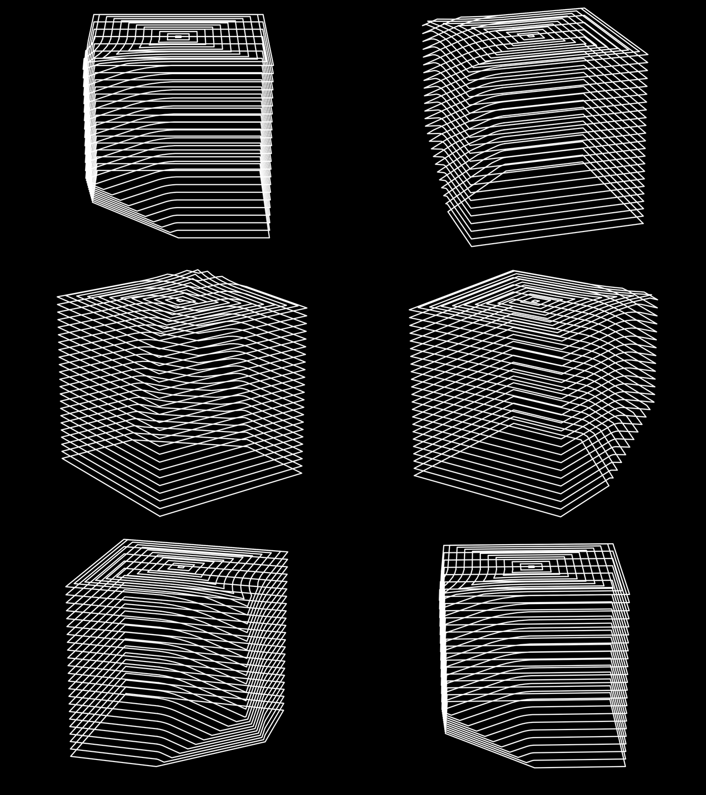
Each successive trace loop remains equidistant from the previous.
Note how the angled snub portion does not have stair-stepping
Support and Infill
No Support Nor Infill
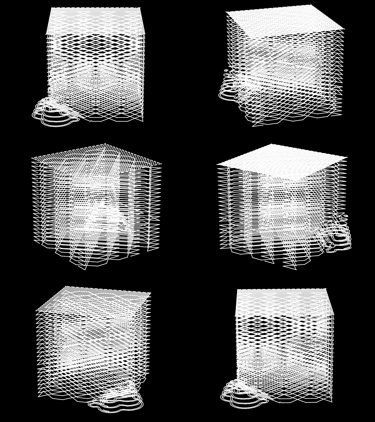

Infill is also unnecessary because it is just internal (non-breakaway) support
